Cover
All Aboard!
Start With The Basics
Why The Track Is So Important
How Does The Power Supply Work?
Analog
and DCC Explained
Layout Options Explained
Locomotives And Rolling Stock
What Should You Start With?
How Do You Create A Good Layout
More On Layouts and LDE
How to Create Realistic Scenery
Explain Weathering Techniques
How To Repair Problems
BONUS SECTIONS
Frequently Asked Questions
Glossary of Important Terms
Model Railroad Yard Design Explained Step-By-Step
Model Train Layout Track Plans
Garden Railroads
Mastering An Airbrush Step-By-Step
More
Model Railroad Resources
IMPORTANT NOTE: The next few pages contain some reasonably technical information on comparing the two operating systems – Analog and DCC. I thought it important to cover the two systems now, before moving on to discuss other aspects of model railroading. If you are a beginner, you might prefer at this point to jump to the section titled "Layout Options Explained" and return later to this section. You could
choose this option if the next few pages begin to sound a
bit technical for you, depending on what stage you are at
in the hobby. I have tried to explain all the key points in
easy-to-understand words and avoid technical jargon, however
the information is more complex. You decide! |
Explain The Difference Between Analog And DCC Operating Systems
Since the advent of DCC (Digital Command Control), there has been a lot of confusion between DCC and Analog model railway operating systems. The big question is; what's the difference between the two systems and what are the advantages/disadvantages in simple, easy to understand terms?
|
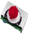
Analog controller |
Quick Tip: Using an Analog control requires a basic knowledge of electricity and how electric circuits work. When you have a large Analog layout the wiring can become very complicated and it is worthwhile to have good drawings (schematics) showing how the wiring is done. This is strongly recommended for all model railway wiring on any layout larger than a 4x8 ft board (1x2 meters). Larger layouts should be broken down into electrical sections or blocks to achieve better running. |
What
Are The Advantages & Disadvantages
Of An Analog Operating System?
Advantage #1: An analog model is cheap and simple to install for simple layouts.
Disadvantage #1: If two locomotives are on the powered section of track, then both will move in the same direction. There are ways to take control of each train individually, but for a beginner, it is rather complicated. The basic method used has been block wiring. The model railroad layout is divided up into electrical blocks. Each one of these blocks can control one locomotive. A cab (or throttle) is used to control each train. Arrays of selector switches connect each block. This method of control is also called "cab control."
Probably the most ingenious method of cab control is the one called progressive cab control. As a train moves around the model railroad layout, the connection between the cab and the block is automatically switched by relays to the next block, and the present block is released for another train to use.
Disadvantage
#2: With the analog system, the majority of your time
will be spent throwing toggle switches to keep your train running. But,
that is not necessarily a disadvantage, because many model train enthusiasts
enjoy doing precisely that.
Return
to top of page
Analogue layout wiring involves the traditional methods of cable and switches to operate the layout. The three principal areas of layout wiring are:
1. Track section
wiring - getting the power to the locomotives.
2. Turnout motor wiring - electric turnout motors (points).
3. Signal wiring.
When wiring a layout it is important to focus on each of the three areas individually to avoid an electrical mistakes.
To operate more than one train at the same time you will need to divide your analog layout in several sections called 'blocks'. A switch wired to each block enables you to select the controller. To run your train on the same controller over the whole of a selected route needs selector switches in the correct positions. To achieve this requires extra wiring. Making a drawing (schematic) of the wiring will become very useful for fault-finding. A good schematic should help you to locate the fault more quickly.
Before we move onto looking
at DCC lets take a closer look at the three principal areas of layout
wiring already mentioned.
1. Track Section Wiring
Correct wiring allows locomotives
to run around a layout at low speed. The sight of a locomotive moving
slowly across plain track and turnouts is what model railroaders like
to see happen. Unfortunately, for many modelers that is a dream rather
than a reality. The running performance (or lack of) is usually due to
one or more of these factors:
a) Track material & careful fixing
Smooth running necessitates the careful fixing of your track, ensuring it is flat, level and correctly joined. Forcing the track together isn't recommended. Generally, if the track looks good after close inspection, and if it is smooth to the touch, then smooth running should result. Irregularities in the track will become evident when you start running your trains. For this reason it is important to spend more time initially by carefully fixing the track, rather than making mistakes that could cause permanent damage to the track.
b) Wiring methods
Several factors can influence a decision on the best type of track wiring for a particular layout. For example; who is going to use the layout, what size is the layout and what will the locomotive movements require? On small layouts the wiring can be kept simple and easy to understand. On larger layouts it is best to break the layout down into electrical sections or blocks determined by the running requirements of the layout.
You can isolate the blocks using insulated/plastic rail joiners (or a simple break in the track) and feed each block from a switch allowing each block to be switched off. Use a common return system where two controllers are in use (check to see that your controller is suitable) allowing locomotives to cross between controllers without having to increase the speed.
Consider using two-way switches with a 'center off' position as it gives more operational freedom on the layout. This allows each block to be controlled by either controller or to be switched off.
Quick Tip: PTM (push to make) switches located to control the ends of sidings can be another useful addition to track wiring. Use a single cut in one rail approximately 12 inches (300mm) from the end with a PTM switch across the break. This should automatically stop a locomotive as it crosses the break preventing damage to the buffers. Another advantage is that the break allows a locomotive to be stored at the end whilst moving another locomotive on the same track. To move the stored locomotive simply press the PTM switch. |
c) Controller type
When compared to the more modern electronic controllers, the older 'rheostat' controllers were not as reliable in performing at low speeds.
It is a bit like comparing any 1970's electrical appliance with its modern day counterpart. A controller that is twenty or thirty years old is likely to have its limitations.
The suitability for the
required task is another point to consider. The controller should be appropriate
to the size of the layout and to the type and number of trains running
on the layout. If the layout is underpowered, then poor performance and
even damage to the transformer may result.
d) Locomotive mechanism
- motor, gears, collectors (pick-ups) & wheels.
Better quality motors, gears and wheels are readily available. As with controllers, the technology used in modern day locomotives has improved greatly. So again, a locomotive purchased twenty or thirty years ago can't be expected to perform as well as its modern day counterpart. Although, in saying that, a lot does depend on the quality of the locomotive you purchase and how much money you are prepared to invest in buying a locomotive or its components.
e) Dirt & Grime
This point is mentioned elsewhere, but it is worth stressing again. Cleanliness is essential for smooth running. Dirt can accumulate on the track, locomotive wheels and axles, and within the locomotive mechanism, particularly on the commutator of the motor. The fact is; dirt and grime are major causes of non-running and poor running. Even the best quality track, controllers and mechanisms will be adversely affected by dirt and grime. Regular cleaning of the track and servicing of your locomotives is therefore essential.
Quick Tip: How To Clean A Commutator? A commutator in good condition will usually appear copper colored with some dark areas of contact between brush and commutator. For a motor to run efficiently it needs a clean commutator. A train with a clean commutator will run better and have more power. Cleaning
a commutator doesn't need to be difficult. One simple cleaning method
is to rub an eraser over the surface of the commutator until it's
polished clean. Another method is to rub some fine sandpaper over
the commutator surface. |
Quick
Tip: If the brushes are worn, replace them! Brushes are one of the most critical components in your motor. The brushes need to properly contact with the commutator otherwise there is a risk of excessive heat, arching and damage to the commutator. The greater the surface area contacting the commutator, the more current (more power) delivered to the armature. Keeping the brush face FLAT (it contacts the commutator), is the key to good brush performance. |
2. Turnout Motor Wiring
Walking up and down the layout to
change turnouts can wear out your shoe leather very quickly. However,
this can be avoided by installing turnout motors.
Most turnout motors function using two solenoids which move a bolt connected to the turnout motor. This changes the direction of the turnout.
To prevent damage to the solenoid coils, the power supply to the solenoid has to be 'non-latched' or momentary. One method is to use a schematic track drawing with studs touched by a probe to complete the circuit. The studs can be replaced by 'push to make switches' or biased (momentary) toggle switches.
Quick Tip: A device called a Capacitor Discharge Unit (CDU) can be fitted. This usually results in greater efficiency and most layouts only need one CDU regardless of the number of turnout motors on the layout. The CDU works by increasing the power available to the switching method. This virtually eliminating 'sticking' solenoids, prevents damage to coils. Also, in most instances, it allows for more than one turnout motor to be operated from one switch ie. facing and trailing crossovers. In more advanced
use the solenoid motor and CDU can be combined to produce diode
matrix, allowing complex routes to be set from one switch. |
Some model railway layouts still use the older semaphore signals, whilst other layouts use color light signals.
Electrically operated semaphore signals can add to the historical effect, but they can be expensive and do require an accurate mechanical mechanism (often electric motor controlled) to activate the fragile signal arm.
Color light signals are more common and much easier to wire because they don't require any mechanical control. A simple two way switch (SPDT) will do the job for a simple green or red light option. Signals, however, rarely operate alone because one signal showing the all clear, will mean that another somewhere on the layout will show a 'caution' or 'stop' signal. This is where interlocking becomes useful. Accessory switches attached to turnout motors, can assist with the control of signals (particularly color light), usually via a relay(s). The turnout positions on the layout can then control all the related signal options.
Return to top of page
|
|
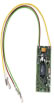
Decoders are the electronics that go within each locomotive. Decoders operate the locomotives motor and can control the locomotives functions. Some decoders have only a single light function whilst others have 8 functions. The more functions the more items you can control. You will need to decide how many functions you want. It is worth pointing out that if your command station can only send one function and you have decoders with 8, that command station can still only control a single function.
Decoders also have various motor control features. The more basic ones have only speed and direction control features. The more advanced ones might have, for example, acceleration, deceleration, consist control, and motor back emf (electromotive force) control.
Quick Tip: Back Emf is somewhat like the speed cruise control in your car. The decoder constantly determines the needs of the motor and adjusts it accordingly. The speed can be set to a predetermined level so that the train will operate at that speed independent of load or grade (until wheel slip). Therefore, when the train comes to a hill it would maintain the same speed going up the hill as on the flat. If you like slow operation or have a lot of grades, then 'back emf' could be worth considering. If you have few grades and like to operate at high speeds then 'back emf' may not be worth the extra expense. |
With a DCC system you can even have whistles and sounds. You can control the whistle, bell, air pump, brake, dynamo, blow down, coupler clanking, horns, and the diesel engine rumble. You can even get the sound of a fireman shoveling coal, an air compressor, oiling and more.
What
Are The Advantages & Disadvantages
Of A Digital Command Control (DCC)
Operating System?
Advantage
#1: DCC is able to communicate with
each locomotive individually,
allowing each to be given its own commands independent
of the operation of other locomotives. It does not need the track to
be divided into sections.
Advantage #2: A
DCC system may give you more fun operating your trains because you'll
have more time to watch the trains. With DCC, you don't have toggle switches,
so you can watch the trains run instead of messing with a control panel
full of toggle switches. Everyone is different and it is important to
select the system that you personally enjoy operating. If you enjoy toggle
switches then stick with analog.
Advantage #3: Wiring is much easier with DCC. The larger, more complex layouts will still require a fair amount of wiring and will be complex, however, it should be far less complex, and much easier than wiring the equivalent layout with an analog system.
Advantage #4: DCC provides a more accurate signal, and is more open for expansion to future technologies.
Advantage #5: DCC is easier to upgrade.
Disadvantage #1: DCC controls are more expensive.
Disadvantage #2: Each locomotive to be used with DCC must be equipped with a decoder. At approximately $30+ each (not including installation, which can range for $10 to $20+ per locomotive), it could be a big expense if you have several locomotives.
Disadvantage #3: Not all locomotives can be converted from analog to DCC.
What Does A DCC System Include?
There are five components in a basic DCC system:
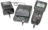
1. Command Station
The command station is the brains of any DCC system (besides the engineer!). The command station is basically a dedicated computer that communicates with all other parts of the DCC system. The command station processes the signals from one or more throttles, and transmits them to the track via a 'booster'. The throttles connect to the command station either directly via the socket on the unit or via a 'network' for more than one throttle.
Take care when selecting the brand and model of command station, because it is the key to selecting the type of throttle controls as well as system features that can be expanded on.
|
|
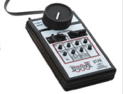
In general, use any hand throttle can control up to a reasonable number of locomotives at any one time. There are various differences between the way that each locomotive is selected and some have rotary speed knobs whilst others use a push-button type speed selection.
Locomotive functions such as lights, smoke units, sound etc are selected from the hand throttles. The number of functions in use depends completely on the decoder fitted to the locomotive. In the majority of cases only 3 or 4 functions are available and used, sometimes only 1 or 2, but with the increasing number of specialized sound units becoming available, more functions are necessary to control all of the possibilities.
So, as you can see there are choices to be made depending on your own personal requirements (and available budget). Each brand of DCC system requires their own brand of throttle or engineer’s cab, and their specific type of throttle to command station wiring interface. So, choose carefully, because the brands don't easily intermix.
3. Boosters
A booster (or power station) amplifies the power of the communication signals from the command station into power applied to the track. It is important to note that almost all boosters require an external power supply. Also note that the ampere rating of the booster and power supply will limit how many locos you can run at the same time.
Track wiring for DCC needs to be robust, because power from the booster must be able to reach and operate all the moving locomotives simultaneously.
Having separate boosters is usually a good idea, because the total locomotive current draw could exceed the rating of a single booster. With separate boosters you can create separate 'power districts' which have independent supply so that a fault on one doesn't shut down the whole layout. Each power district must be fed from a power booster. Separate boosters do not process signals, but need to be linked to a command station via 2 wires known as the 'command bus' in order to pass signals to the track in its power district.
There is no limit to the number of districts, and boosters, that can be used on a layout. Each booster is usually supplied form a separate transformer. One transformer can supply more than one booster, but the maximum current is then limited to the transformers capacity.
Starter systems often combine a command station and booster into one box.
For example: the Bachmann
EZ DCC has everything in one box; the Digitrax Zephyr' has throttle and
command station in one box; and the Lenz LV100 has the booster and command
station in one box.
Some boosters are available separately
and, depending on the setup, may be controllable from a command station
of a different brand.
4. Power Supply
To clarify one point; DCC puts ‘fixed’ electrical power on the track whereas with standard DC controls, the ‘throttle’ puts variable voltage power on the track. With DCC, the decoder inside each locomotive receives track power AND listens to commands sent out over the rails from the command station. |
Before you purchase your DCC system check to see if the power supply is included. With many DCC equipment systems the power source must be purchased separately. An additional power supply is usually required with each additional booster.
|
|
Each decoder has to have a unique address so that the controller can individually identify it. This explains why every DCC controlled locomotive must have its own decoder. Almost any brand of loco decoder should work with any brand of DCC command station/throttle equipment.
As a rule, DCC systems can control any decoder. Therefore, you are not restricted to purchasing all the locomotive decoders from the same manufacturer as the command station.
On the other hand, there is an incompatibility between the US and European systems in the way that multiple hand throttles can be used with a command station. The systems, known as LocoNet by Digitrax and XpressNet by Lenz, are networks that use different protocols and connections to communicate, hence you can't mix the two manufacturers. This means that a hand throttle from Digitrax will not be able to work with a Lenz system or vice-versa.
Remember; the whole reason for DCC is to allow multiple locos
to operate independently on the same track, without having to divide up
the layout into complicated electrical control blocks.
A computer is generally NOT required
for DCC operation although some “techies” with do-it-yourself
DCC systems use of a computer for signaling etc.
Return
to top of page
NONE of the commercial systems require a computer and therefore, no major programming is required. The only thing you need to do is configure the addresses of each locomotive.
This refers to entering data into a locomotive to determine how it behaves when selected from the hand throttle. In general the locomotive will need an address entered, a loco number, and owners may typically want to set the amount of acceleration and braking delays.
There are also many other items that can be set within the locomotive decoder. Each of the settings that can be programmed within a decoder is known as a Configuration Variable (CV).
There are two ways that programming can be carried out within DCC:
1. Service Mode
Service mode programming is carried out on a dedicated programming track and has the ability to change any of the CVs for the decoder. In this method a separate connection is taken from the system control unit to the dedicated track. Only a locomotive on the programming track can be configured in this mode.
2. Operations
Mode
In this mode the locomotive
to be programmed can be anywhere on the layout and must be addressed individually
to ensure that any other locomotive on the layout is not affected. It
is important to note that some older decoders do not allow operations
mode programming. Also, some systems, and some decoders, will not allow
locomotive addresses to be changed during operations mode programming.
Be aware that most systems restrict the amount of current draw available to the programming track. The reason is to prevent an excessive overloading or burn-out of a decoder when programming.
How To Know If A Locomotive Has A Decoder Fitted
When purchasing a locomotive with a decoder installed, look for the wording "DCC equipped", or "Factory installed decoder", or "W/DCC", or wording like that.
Be careful though, because the words "DCC Ready" usually means that the locomotive is capable of having a decoder installed and that one is NOT already installed. I repeat, "DCC ready" usually means there is NO decoder fitted, but the wiring inside the locomotive is terminated with a socket, ready for addition of a "Plug and Play" decoder. This is an easy installation, no soldering.
If you are still unsure whether or not a locomotive has DCC status, you can try this test. Place the locomotive on the program track of a DCC system. See if the command station can read CVs... and if it can't... then no decoder is fitted. Also, without a decoder fitted, the loco would “hum” with the throttle set at "0".
If the locomotive responds to the throttle on a DC system, then either there is NO decoder, or the locomotive may have a decoder that has analog operation enabled.
If in doubt, it is always best to get clarification from the hobby store staff, or from the manufacturer or person supplying the locomotive.
A common question is whether or not you can control turnouts with DCC.
The simple answer is yes. You can even have the turnouts report the turnout status to a central computer. You can use this to operate signals or control train movements. Turnouts can be controlled with push buttons or from your throttle.
One thing to remember, however, is that with a DCC system, multiple trains may come to a stop at the same time. This can be particularly frustrating when several people are involved.
Trains shorting out on a turnout could be caused by a number of things. Something could be wrong with a locomotive (or rolling stock), or perhaps the points on the turnout may be too close. Fixing the turnout, the rolling stock, or the locomotive can be a real challenge if your layout is not in a climate controlled room. Temperature and humidity can make perfection an unattainable goal. To avoid potential problems; try to have all your turnouts, locomotives, and rolling stock in good condition.
It is usually best to start your DCC system using the five basic components already mentioned. As your model railroad grows, and you become familiar with DCC operation, you may want to add more DCC equipment to your layout such as:
- more power supplies & boosters
- additional throttles for multiple users (same brand)
- remote plug-in panels for walk-around throttles
- auto-reversing track controllers
- accessory decoders for DCC operation of track switches (turnouts)
- electronic circuit breakers for separation of track circuits into multiple power districts
- or even radio equipped throttle adapters
Return to top of page
© 2006 Robert
Anderson, Market Leaders Ebooks, all
rights reserved